The Role of Electronegativity and Conjugation in Bonding
by Ari Wagen and Jonathon Vandezande · Dec 13, 2024
Last week, we launched a new orbitals workflow. This workflow calculates molecular orbitals, electron density, electrostatic potential, atom-centered charge, bond orders, and multipole moments. You can read more about the launch on our newsletter or try running the new workflow on Rowan's web platform.
Viewing orbitals and isosurfaces can be super insightful—but it can also be hard to know what to look for and how to interpret surfaces. To help with this, we're writing a series of blog posts that will break down the basics of working with orbitals and isosurfaces.
And to give credit where it's certainly due: a lot of this content comes from The Molecular Modeling Workbook for Organic Chemistry by Warren J. Hehre, Alan J. Shusterman, and Janet E. Nelson (Internet Archive, Amazon).
Ionic and Covalent Bonds
Not all bonds share their "shared" electron pair equally. In covalent bonds, the electron pair is shared more or less equally between the bonded atoms. In ionic bonds, the electron pair is entirely on one atom. In intermediate "partially ionic" or "polar covalent" bonds, the electron distribution is in between 50/50 and 100/0.
By plotting the electron densities, we can directly visualize where electrons are, helping us make sense of the trend connecting electronegativity (EN) to the covalent/polar covalent/ionic spectrum of bonds.
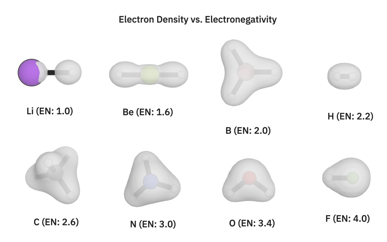
You can view all of these calculations yourself in this shared Rowan folder. These isosurfaces were computed at the B97-3c level of theory, and show the electron density of each respective structure with a 0.05 e/Bohr^3 cutoff.
Looking at H2's electron density (top right corner), we see a perfectly covalent bond where the electrons are shared equally between the hydrogens. Looking at lithium hydride and beryllium hydride, we see that the electron density around the hydrogens is slightly larger than in the H2 case. (In the case of lithium hydride, the electron density around lithium is smaller than our visualization of the lithium atom itself.) On the other end of the spectrum, we see that the electron density around the hydrogen in hydrogen fluoride is smaller than in the H2 case.
If we refer to each atom's electronegativity value, these electron density maps make sense. Lithium has a much lower electronegativity value than hydrogen, so hydrogen attracts the bonded electrons. In the case of hydrogen gas, the two hydrogens have the same electronegativity, thus sharing the bonded electron pair equally. In hydrogen fluoride, the fluorine attracts the electrons, pulling them away from the hydrogen.
Small differences in electronegativity cause bonds to have more covalent character. Large differences in electronegativity lead to more ionic-type bonding. For reference, NaCl, a fully ionic bond, is made up of sodium (EN: 0.93) and chlorine (EN: 3.16).
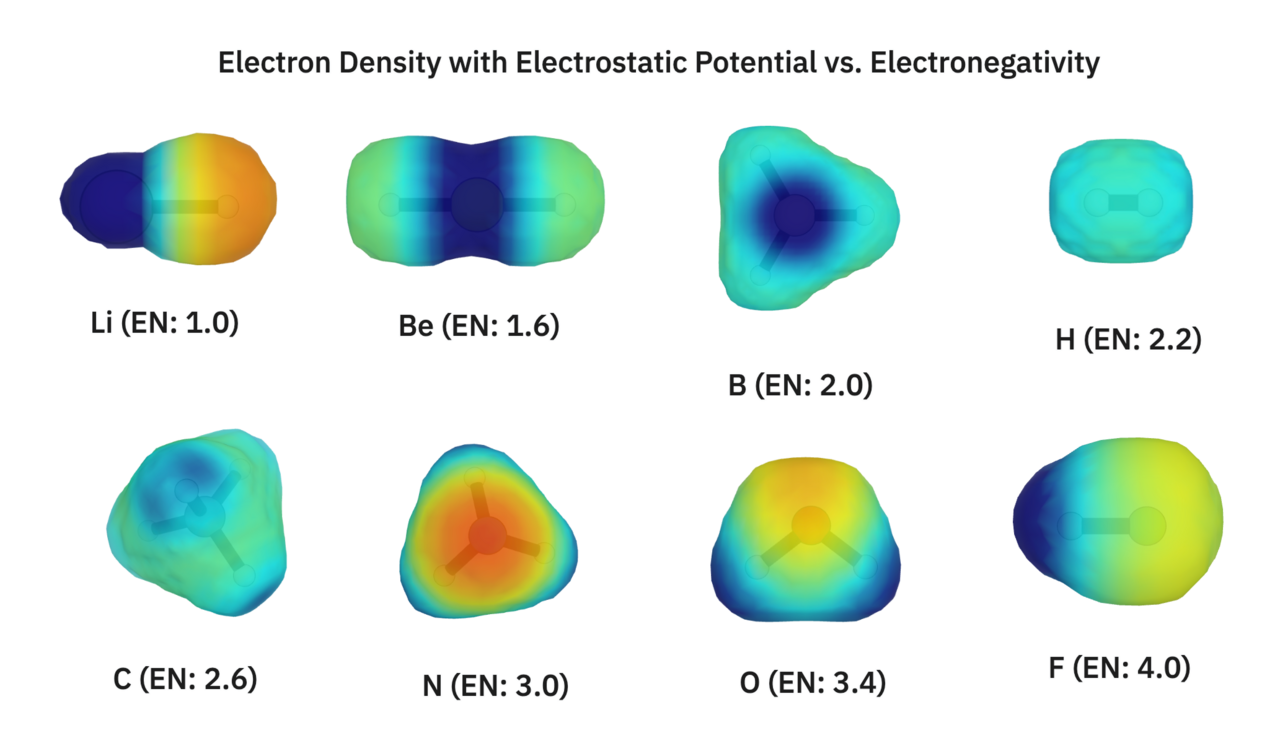
We'll also visualize all of these same structures with a lower (0.01 e/Bohr^3) electron density cutoff, colored on electrostatic potential.
To quote our newsletter:
Electrostatic potential gives us an idea of a molecule's charge distribution. Areas of negative electrostatic potential (shown in red) correspond to areas that will attract positive charges (electrophiles), while areas of positive electrostatic potential (shown in blue) correspond to areas that will attract negative charges (nucleophiles).
Electrostatic potential is often just referred to as charge. A quick visual inspection shows that more electronegative elements create areas of negative charge.
Key Takeaways
- Small electronegativity differences lead to covalent bonds.
- Somewhat large electronegativity differences lead to polar covalent bonds.
- Very large electronegativity differences lead to ionic bonds.
- Electronegative atoms attract electrons, creating areas with negative charge.
Hydrocarbon Bond Lengths
To study bond lengths in simple hydrocarbons, we'll start by running optimizations on ethane, ethene, and ethyne to serve as references:
- Ethane has a C–C bond length of 1.519 Å.
- Ethene has a C=C bond length of 1.324 Å.
- Ethyne has a C≡C bond length of 1.200 Å.
All of the structures in this section were optimized with B97-3c; orbitals were also calculated with B97-3c. You can view them all it this shared Rowan folder. The bond lengths reported in this section are from the B97-3c optimized structures.
To quickly touch on orbital basics in broad strokes, I'll quote our newsletter:
Orbital surfaces that touch only one atom are called "nonbonding." Orbitals that touch two atoms are "bonding," and adding electrons to these orbitals will strengthen the corresponding bonds. If an orbital contains a node (a gap between a red surface and a blue surface) that divides a bond, it is "anti-bonding"; adding electrons to these orbitals will weaken the corresponding bonds.
The first system we'll look at is 1,3-butadiene (C=C–C=C). The double bonds in this structure are slightly longer than ethene's (1.333 Å) while the single bond is slightly shorter than ethane's (1.456 Å). Looking at 1,3-butadiene's orbitals can give us an idea of why:
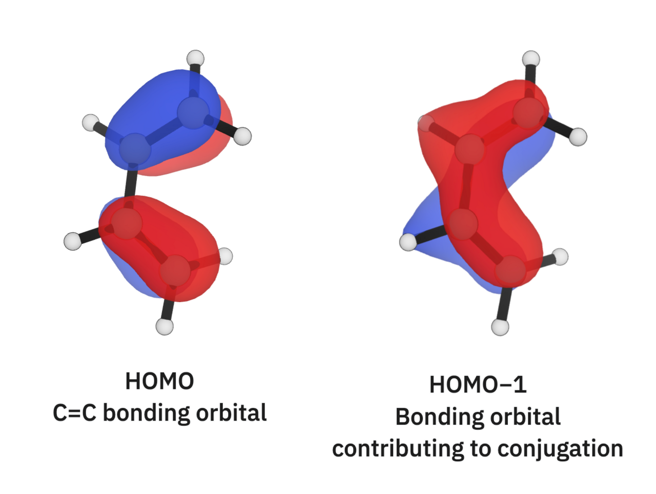
I'd characterize butadiene's highest occupied molecular orbital (HOMO) as "bonding." The orbital isosurfaces connect each C=C bond in the structure, creating the traditional double bonds as characterized in the C=C–C=C line representation. The HOMO−1 orbital, however, shows a "conjugated" orbital that touches all four carbons! This gives the single bond in butadiene a bit of "double-bond character," causing it to be longer than the ethane C–C bond and the double bonds to be shorter than ethene's C=C bond. This is reflected in the computed Mayer bond orders too: the single bond has a computed bond order of 1.09, and the double bonds have computed bond orders of 1.91.
We'll next look at 1,3-butadiyne (C≡C–C≡C). After looking at 1,3-butadiyne, we might expect to see a shorter single bond than in ethane and longer triple bonds than in ethyne. Looking at it's bond lengths, we can confirm this; the C–C bond length is butadiyne is 1.352 Å (much shorter than ethane's) while the C≡C bond lengths are 1.210 Å (slightly longer than ethyne's). Looking at its orbitals, we can see that the HOMO−2 and HOMO−3 orbitals are responsible for this conjugated character:
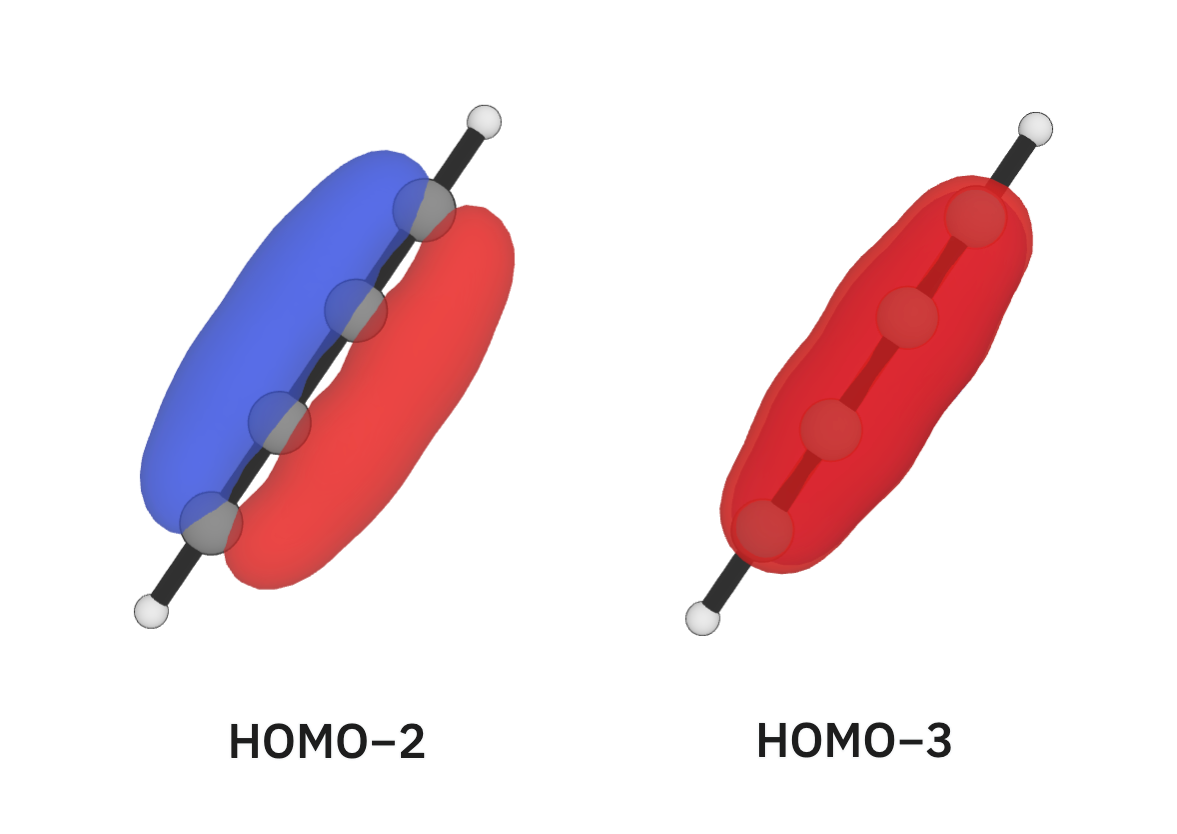
Next, we'll look at allene (C=C=C). Allene's C=C bonds are 1.299 Å long, shorter than ethene's. Unsurprisingly, looking at allene's occupied orbitals can help use visualize this conjugation:
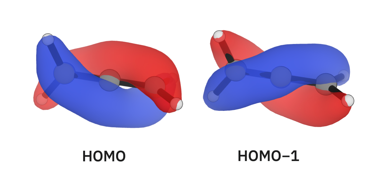
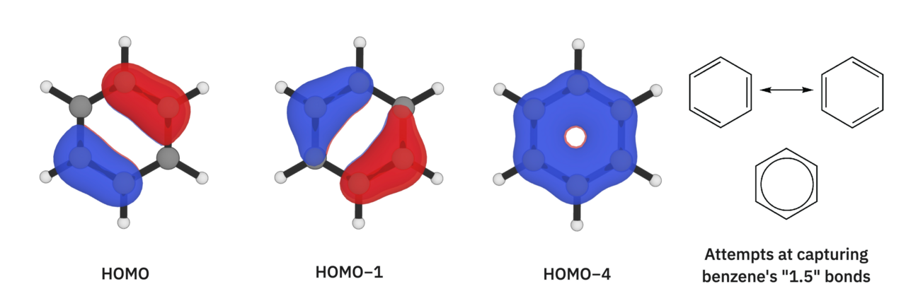
While we're on this topic, benzene's bond lengths are another interesting example—each C–C bond in benzene is 1.388 Å long, making each bond more like a "1.5" bond than a single or double bond. Here are some of benzene's orbitals:
Finally, we'll turn our attention to the allyl cation, the allyl radical, and the allyl anion. These structures have the same atoms, but different numbers of electrons. This means that they assign different numbers of electrons to one orbital, leading to differences in their geometries:
- The C–C bonds in the allyl cation are 1.376 Å long, and the C–C–C angle is 119°.
- The C–C bonds in the allyl radical are 1.377 Å long, and the C–C–C angle is 125°.
- The C–C bonds in the allyl anion are 1.388 Å long, and the C–C–C angle is 133°.
By visualizing the relevant orbital (visually, we can see it's the same for all of the systems), we can understand how its occupation is affecting their geometries:
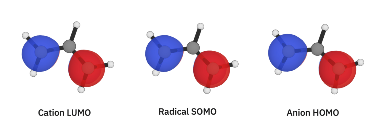
This orbital has one node that's right on the middle carbon. If I were trying to put this into a bonding/non-bonding/anti-bonding bucket, I would call it "anti-bonding." In the allyl cation, this orbital is unoccupied (it has no electrons in it), so it doesn't affect the molecule's geometry at all. Adding electrons to this orbital makes the system less conjugated, which is why we see the C–C bond lengths get longer and the C–C–C angle get wider as we add electrons. There's a lot more to say here about π orbitals that we don't have space for; to learn more about this specific system, we'd recommend checking out this Master Organic Chemistry article.
Key Takeaways
- Orbitals that only touch one atom are "non-bonding." Adding electrons to these orbitals won't significantly affect a structure's geometry.
- Orbitals that touch two atoms are "bonding." Adding electrons to these orbitals will strengthen bonds.
- Orbitals with a node between two atoms are "anti-bonding." Adding electrons to these orbitals will weaken bonds.
- Bonding orbitals that touch multiple atoms contribute to "conjugation." Conjugation leads to non-traditional/non-integer bond orders.

